FSAE Blog 1 - Building a Formula Car: Wiring Harness
2026-01-19 | By Antonio Velasco
Anteater Formula Racing is a student-run engineering project at UC Irvine. The objective is to design, manufacture, and test a Formula-style car in less than a year to compete yearly in the Formula Society of Automotive Engineers competition in Michigan (FSAE). Once in Michigan, the car is judged by industry professionals against a variety of criteria, including static/dynamic events, presentation, engineering design, and many more. Anteater Formula Racing consists of approximately fifty students from varying engineering backgrounds working on different vehicle subsystems, ranging from chassis, suspension, aerodynamics, electronics, and many more. Learn more here!
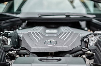
Popping the hood of any car reveals an organized chaos of colored wires, connectors, and various electronic components strung together across the engine like veins across a body. This neat yet complex mess is referred to as a wiring harness, and is one of the most essential (and often underrated) systems within a car.
Every year, when Anteater Formula Racing (AFR) develops the racecar for the upcoming FSAE competition in May, our Electrical Subteam designs and manufactures the wiring harness from scratch.
What is a Wiring Harness?
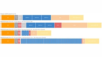
For a car’s engine to function properly, a variety of sensors, actuators, and more need to function accurately and on time. Moreover, each of the components needs to communicate with each other to operate properly. For example, the steering wheel acts as an interface (like an input device) between the driver and the wheels (an output device based on the input). Everything in between, like the ECU or the gears, processes that input signal. The wiring harness establishes this interaction and facilitates actions between every part of the car, with hundreds of sensors reporting signals and data, and hundreds of devices acting on it. Without a robust and efficient wiring harness, none of the components would communicate effectively, and the electrical system would be rendered useless.
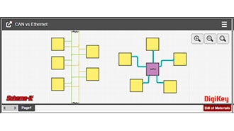
Here’s just one of twelve pages of what our diagram in AutoCAD EL looks like:

A bit complicated, right? Here’s what the wiring harness looks like after everything’s done:

This chaos gets bundled together into a singular, neat, and elegant solution to be placed into the car. This year, we’re looking to improve on it and include some new features to make it easier to debug and place onto the car.
Design Goals
This year, in our pursuit to continuously improve the car, we had these goals in addition to our ongoing design requirements:
- Improve Serviceability: One of the main issues with our wiring harness in the past was that, while we can manufacture it and install it into the vehicle, it becomes a nuisance to take off and troubleshoot if any issues arise. In order to make it easier, we’re planning on using connectors to section off the wiring harness and make it into multiple pieces. That way, we can easily take it off the vehicle and isolate problems as they arise.
- Efficiency & Optimization: When a lot of wires are used, the wiring harness easily gets complicated and hard to work with. To optimize the electrical system, we’re aiming to use fewer wires and cut out any redundant components. Additionally, smaller wires would be used when applicable (as larger wires are bulky and heavy).
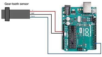
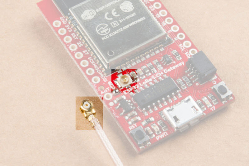
- Addition of New Sensors: To improve the reliability and the driver experience of the car, new sensors, like wheel speed sensors and certain fluid temperature sensors, will be added. This will also provide us with much-needed data to tune the car and to find major faults before they occur.
Initial Manufacturing
The initial manufacturing of a wiring harness included a lot of measuring and overall planning. After we got our designs down in AutoCAD EL, we placed our sensors and components across a table and mapped out what it should generally look like when we’re complete. Then we got down to the nitty-gritty of soldering everything together and sorting the wires:

Along the way, we made sure to check for continuity across each line and to verify each sensor one at a time. A major issue that we found was that our crimps were often not very reliable and could easily come off if we did not properly secure them.
Blockers & Next Steps
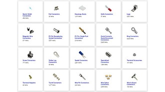
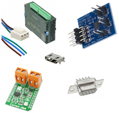
In order to get through the issue of our wire connections not sticking, we had ordered some new, more reliable crimps that also included a solder piece in the middle. You can get those on DigiKey here!
We also established a policy to use as few crimps as possible and to measure out the wires as best as possible to begin with.
Continuity seemed fine for the most part, so the next step is to hook it up to a battery and boot it up! After we work on some power mitigations, like adding fuses and ensuring that everything is safe, we’ll do some cycling and start the real troubleshooting. Once that’s complete, we’ll section everything off with connectors and then move to looming everything together for the final product. Stay tuned!